


Chitraansh Chaudhary
Wireless power transfer (WPT) has emerged as a transformative technology, enabling the transmission of electrical energy without physical connectors. This abstract explores the primary technologies driving WPT, including inductive coupling, magnetic resonance coupling, and radio-frequency transmission. Each method’s underlying principles, advantages, and limitations are examined. The paper also discusses current standards governing WPT systems and highlights diverse applications across industries such as consumer electronics, healthcare, and automotive sectors. Furthermore, the challenges faced in terms of efficiency, distance, and safety are outlined, alongside future research directions aimed at enhancing performance and expanding the practical uses of WPT.
1. INTRODUCTION
The Wireless Power Transmission (WPT) method is a groundbreaking technology that removes the necessity for wires or physical connections to transfer electrical energy from a power source to a device or appliance. This advanced approach to power distribution addresses the limitations of traditional wired systems, such as bulkiness, limited mobility, and wear and tear on connectors. WPT includes various techniques such as inductive coupling, resonant inductive coupling, radio frequency power transfer, and laser-based power transfer, each serving unique applications and operating within specific ranges. Regulatory bodies like the Society of Automotive Engineers (SAE), the Wireless Power Consortium (WPC), and the AirFuel Alliance provide global standards and guidelines for WPT technology, ensuring its safe and efficient integration across different sectors. Potential applications of WPT span consumer electronics, electric vehicles, medical devices, and industrial environments. With continued research and development, WPT has the potential to transform power distribution, making it simpler, safer, and more adaptable for various industries.
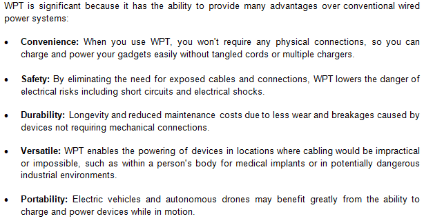
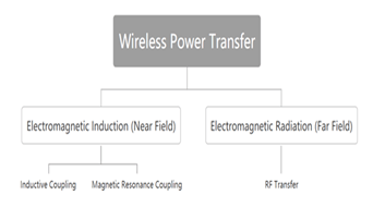
WPT (Wireless Power Transfer) offers several advantages over conventional power transfer methods: a wide charging power range, the ability to fully seal electronic devices by eliminating the need for power ports, increased product lifespan due to reduced physical damage risk from impacts on ports, and simplified placement and charging without the use of wires. It is compatible with all major brands of portable devices. The two primary categories of WPT technologies, based on the distance of their transmission, are electromagnetic radiation, which operates in the far field, and electromagnetic induction, which operates in the near field. An example of the classification is given. A few millilitres to a few centimetres is the range of far-field power transfer, in contrast to the few metres to several kilometres used for effective transmission distance in far-field power transmission.
After a quick overview of WPT in Part I, the second portion delves into the inner workings of the most popular WPT technologies. Part II ends with a comparison of the features of different technologies. Section III presents the three WPT applications.
During the latter half of the 19th century and the early 20th century, Nikola Tesla was a pioneering inventor who developed the concept of wireless power transfer. Using resonant inductive coupling and high-frequency AC, Tesla pioneered early experiments in wireless electrical transmission, demonstrating promising feasibility. However, practical implementation was hindered by substantial economic and technological challenges at the time.
In recent decades, academic and industrial interest in WPT has surged, driven by advancements in electronics, electromagnetic theory, and materials research. These advancements have significantly improved the efficiency, range, and safety of WPT systems, unlocking new potential applications and making WPT more valuable than ever before.
1.1 Importance and Benefits
1.2 Technologies of Wireless Power Transfer
Wireless Power Transfer (WPT) encompasses a range of technologies, each grounded in unique physical principles and tailored for specific applications:
- Inductive coupling: Relies on magnetic fields to transfer power between closely aligned coils, suitable for short-range applications like charging pads.
- Resonant Inductive Coupling: Enhances inductive coupling by matching resonance frequencies between transmitter and receiver coils, optimizing efficiency over greater distances.
- Radio Frequency (RF) Power Transfer: Uses electromagnetic waves to transmit power, enabling medium-range wireless charging applications.
Laser-Based Power Transfer: Directs focused laser beams to transfer power with precision, suitable for specific applications requiring high efficiency and targeted energy delivery.
2. LITERATURE OF REVIEW
Song (2023) the subject of wireless power transfer (WPT) comes up quite a bit. As a result of its simple designs and implementations, it is also highly commercialised. It is a method by which electrical current may be sent from one transmitter to another over a space between them. The three most popular wireless power transfer technologies inductive coupling, magnetic resonance coupling, and radio-frequency transmission are all covered in detail in this paper. We also provide the most recent implementations. In an effort to reduce prices, improve device transmission length, and miniaturise gadget complexity, current implementations of popular technologies are facing some obstacles that might be considered as future research trends.
Van et al. (2022) when you need to charge your gadget from a distance or without touching it, wireless power transmission is the way to go. In recent years, solutions’ capabilities, diversity, and maturity have been significantly enhanced via research and development. The current status of several technical topics, such as acoustic technologies, electromagnetic linked and uncoupled systems, and more, is thoroughly covered in this study. Methods for converting milliwatts to megawatts, using wave principles from kilohertz to terahertz, and across millimetres to kilometres are discussed. It paves the way for new possibilities while also being an appealing charging solution for many current applications. To provide these gadgets with wireless power, a number of different methods have been suggested. The transfer’s efficiency and range are the key obstacles. We emphasise novel ways that use beamforming and UV-assisted techniques. Discussions on operational and implementation details, standards, and safety in relation to regulations are of special interest to designers. Appropriate technical solutions for wireless power transmission are mapped to a broad catalogue of possible uses.
Abdullahi et al. (2019) Numerous innovations in electronic systems and devices used in healthcare, communication, and consumer electronics have been made possible by developments in semiconductor technology and material science. A wireless charging system is defined in this study as a chair-based wearable body warmer. A popular wireless charging standard, Qi, is included into this system. We studied the alignment conditions of a 3 × 3 coil matrix array and a linear three-element coil arrangement by measuring the voltage produced in a coil as a performance indicator. For a voltage more than 6.5 V and a power transfer greater than 5 W, the achieved efficiency reaches up to 80%. There are a lot of potential uses for our findings and the method we suggest. This is due to the fact that the wireless charging system outlined here may facilitate the design of a wide variety of electronic systems and devices, including commercial systems, consumer electronics, medical equipment, e-textiles, and sitting places for the old and crippled.Ahmad et al. (2017) there have been several obstacles to the widespread deployment of Wireless electricity Transfer (WPT) systems because of the electromagnetic fields used to transfer electricity. The two facets of its implementation are examined in this document. First, there’s the advancement, development, and use of many technologies utilised in Wireless Power Transfer (WPT), as well as the state of the art in these fields. Next, we have the long-term results. Coil shape, frequency, misalignment, and compensation topologies are some of the system performance aspects covered in the technical chapter. Sustainability thinking incorporates concerns about energy, the environment, and human health. Lastly, the study provides an overview of recent advances in WPT, discusses the health and technological concerns surrounding WPT, and leaves several issues about WPT’s potential impact on sustainable mobility unsolved.
3. WIRELESS POWER TRANSFER TECHNOLOGIES
3.1 Magnetic Inductive Coupling
In 1831, based on the ideas put out by Michael Faraday, a British scientist, Joseph Henry built a telegraph according to his own design that could transmit signals across 2.4 kilometres. Heinrich Hertz, a German scientist, found a way to send electricity through an extremely small air gap in 1888 without the need of wires.
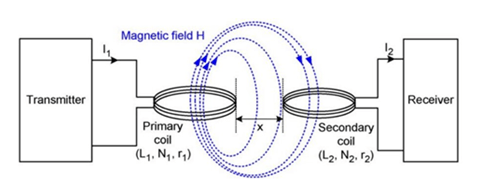
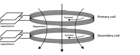
Inductive coupling uses electromagnetic induction to transfer electrical energy between two coils. Similar to transformers, it employs a transmitter connected to a main coil and a receiver tied to a secondary coil. The main coil receives an alternating current. The alternating current transmits the alternating magnetic flux onto the secondary coil across an air gap, in line with Faraday’s law of electromagnetic induction. The formula for magnetic flux linkage is the product of the coil’s flux and the number of turns. Having said that, the air gap can’t serve as an efficient channel for transferring electricity. This causes a rapid weakening of the magnetic flow. The magnetic flux density at x, where x is the distance between the main and secondary coils, is given by Equation (1).
1.
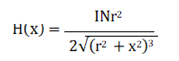
When the charging distance x is squared, the magnetic field strength decreases in a cubical fashion. Improving the alternating current’s amplitude I, the number of turns in the transmitting coil N, and the radius r of the coil will obviously result in a much stronger magnetic field. However, because of the physical limitations of its implementation on portable devices, the number of turns on the coil cannot be freely adjusted. By plugging the values into Equation (1), we can get the optimal coil radius for each gearbox range. Since the charging power diminishes rapidly, inductive coupling usually has an effective charging distance of only a few millimetres. Part III will go into the use of inductive coupling as it pertains to RFID. Although passive RFID has poor power transfer efficiency, it can nevertheless function up to 30 feet away. An ideal power transfer efficiency would have a well-balanced effective transfer distance.
3.2 Magnetic Resonance Coupling
In magnetic resonance coupling, the receiver and transmitter are both tuned to operate at the resonant frequency, and the process is very similar to inductive coupling. The high power transmission efficiency and longer effective distance are both made possible by the tight connection of the two coils. To do this, the coils and capacitors are connected in series. This is achieved by linking capacitors in series with both coils, as shown in Figure 3.
2.

Using equation (2), we can get the resonance frequency at which both coils are operating. Because of its resonance property, the power transmission is relatively immune to environmental and other influences (such as coil alignment, for example). You may use it between one transmitting resonator and several tuned receiving resonators that operate at resonance frequency, and it can charge many devices at once. Some unintended consequences may result from improper calibration of this. Consider the case of competing charge channels.
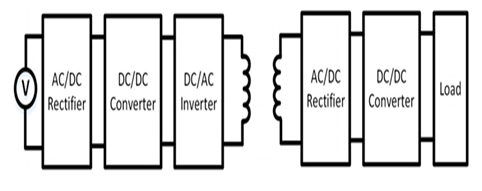
Electromagnetic induction power transfer, often called near-field power transmission, is simplified in Fig. 4. A first AC/DC rectifier, a second DC/DC converter, an inverter that converts DC current to AC current, a third DC/DC converter, and an alternating current/DC rectifier make up the circuit. Initially, a direct current (DC) voltage is created by rectification of an alternating current (AC) voltage. By using a DC/DC converter, the voltage of the DC source may be increased, guaranteeing a respectable transfer efficiency even during air propagation. It is necessary to re-rectify the energy into DC voltage and adjust it to the load’s specifications when it reaches the secondary coil.
At the same kilo-hertz raging frequency, magnetic inductive coupling and magnetic resonance coupling both function. The resonance property also allows for a longer effective power transfer distance than inductive coupling. Because charging portable gadgets is a pain, more room will be required if an advanced LC circuit is employed.
3.3 RF Transfer
Far-field transfer is a subset of radio-frequency transfer technology. Radio waves, a distinct kind of radiation that use a totally different medium, form its basis. Because of the risks associated with electromagnetic wave exposure, high frequency radio waves such as X-rays and infrared rays are not often employed. Radio frequency transmission makes use of electromagnetic waves that oscillate between 300 megahertz and 300 gigahertz.
3.
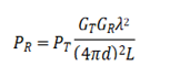
According to Harris [9], Formula (3) is called the gearbox formula. The receiving power (PR), transmitted power (PT), gain (GR), charging distance (d), path loss factor (L), radio wavelength (λ), and transmitter gain (GT) are shown below. Received power attenuates as a function of square of the reciprocal of the charging distance d, showing that RF transmission loses power far more slowly than electromagnetic induction. Thus, the effective power transfer distance is larger for radio frequency (RF) transmissions between a few metres to a few kilometres. It should be remembered that Nikola Tesla conveyed microwave signals 48 km in an experiment he performed in 1896. Electricity for Buffalo was supplied by the project.
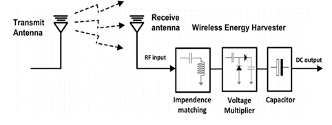
Figure 5 shows the schematic of the RF transfer circuit. In order to transform direct current (DC) from alternating current (AC) at the beginning of the gearbox into radio frequency (RF) power at the conclusion, a rectifier is used. The transmission antenna sends the radio wave to the receiving antenna, which rectifies it into DC before connecting it to the load. An efficient transmission of energy is crucial to the four-part RF energy harvesting system, which also includes an impedance matching circuit and a voltage multiplier. Impedance matching boosts the power transfer rate by mimicking the behaviour of a resonant circuit set to resonance frequency. By connecting a capacitor and a voltage multiplier in series, RF signals may be easily converted to DC voltage. Both of these components are essential for RF transmission and the receiving antenna to work properly.
3.4 WPT technology summary
Three WPT technologies have been described in the three parts that came before this one. The purpose of this section is to summarise and compare various technologies. Here in Table I are the benefits and downsides of each WPT technology. Recalling that inductive and resonance coupling operate in the near-field at kilohertz range, ranging from a few millimetres to a few metres distance, given the preceding material. The radio waves used in radio frequency transmission (RF) work in the far field at frequencies ranging from megahertz to gigahertz. You can charge it effectively between a few metres to many kilometres.
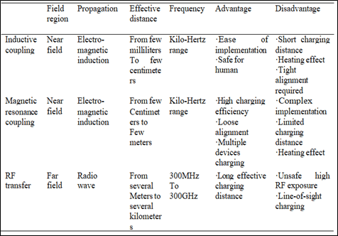
The charging distance is modest with inductive coupling, despite its simplicity and convenience. For optimal power transmission efficiency, precise alignment is also required. Nevertheless, two coils may be loosely aligned thanks to resonance coupling. Both coupling strategies have the major downside of heating the system. When the magnetic flux changes, an induced electromotive force is created in the coil, according to Faraday’s law of induction. A strong current called an eddy current is produced within a conductor when it is sandwiched between two coils; this current causes the conductor to get heated. Reduced efficiency in power transmission is caused by the dissipation of some energy as heat. High RF exposure makes RF transfer dangerous, despite its extended transmission range. Furthermore, RF transmission necessitates line-of-sight charging, which implies that there must be no obstructions in the route between the receiver and transmitter.
4. STANDARDS AND ITS IMPLEMENTATION
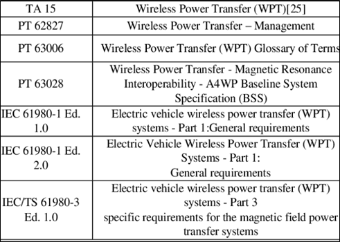
The standard of that era’s research is defined by its standards. A standard cannot be something that is both more accurate and produces better results. The process of standardisation is sequential. The standards are determined by the completion of the process. Table 2 provides a high-level overview of the WPT IEC standards. The names of standards are provided in the standards name table, which is only an introduction. The chart does not include all standards; for example, there are SAE standards and the Qi standard for mobile charging.
5. WIRELESS POWER TRANSFER APPLICATION
5.1 Wireless power supply
Wireless power transfer (WPT) is mostly used for charging electronic devices, such as electric vehicles (EVs) and mobile phones. Wireless charging, which we have previously covered, provides a hassle-free way to charge and may even extend the product’s lifespan.
More and more phones now have efficient wireless charging capabilities, thanks to technological advancements. Future developments will also revolve on the integration of WPT with EVs. Electric vehicle (EV) wireless charging solutions are being adopted by nations that are striving for a greener way of life. Electric vehicles will attract greater investment from brands and corporations, and there will be an increase in the number of parking spots designed just for them. We still need to sort out a few things. as when there is a discrepancy between the vehicle and the transmitter, which reduces the transmission’s efficiency.
The worldwide standardisation of wireless charging has been an area of focus for many organisations. There have been very few proposals for and widespread implementations of mainstream pricing standards. Standards such as Qi, A4WP, and PMA are examples. The Qi standard is going to be the main topic of the next section. Worldwide, wireless charging is currently done according to the Qi standard, which was developed in 2008 by the Wireless Power Consortium (WPC). Brands like Apple, Sony, LG, etc., are approved by the Qi standard. Between these devices, you can be certain that charging will be compatible. Using a voltage range of up to 200 volts and frequencies of 105 kHz to 205 kHz, the Qi standard makes use of magnetic inductive coupling technology. Three different wireless charging approaches have been proposed: guided positioning, free positioning using a single coil, and free positioning using a coil array.
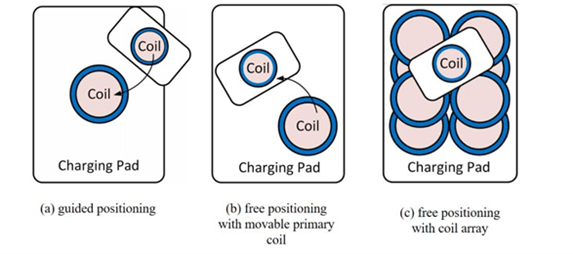
A one-to-one fixed charging system devoid of any moveable components is guided positioning (Fig. 6(a)). Just by putting the charging device on top of the device being charged, inductive coupling between the two coils may be enabled. For optimal charging efficiency, make sure the main coil of the charging pad is parallel to the smartphone. The device is held in place by the Qi processes by the use of magnetic attraction. A little bit of magnet is included in both the load and the charging pad. Because the magnet is a conductor, the charging efficiency will be reduced due to eddy current, which dampens the magnetic field as it propagates through the air. Applying this method, nevertheless, is easy and useful.
Similarly to the one-to-one charging approach, free positioning employing a locomotive primary coil (Fig.6(b)) involves a search device to find the device and motors capable of moving the primary coil on the x and y axes, as well as a moveable primary coil constructed below the charging pad. The area needed to place the circuit underneath the charging pad is not very huge. Underneath the charging pad, you may use either capacitive or inductive coupling techniques. Both the chassis and the motors may be quite expensive and complex.
A method for simultaneously charging several devices is shown in Figure 6(c) using free placement with a coil array. Many coils are constructed under the charging surface to enable free-positioning wireless charging, regardless of the device’s placement or orientation. This methodology is more user-friendly than prior alignment approaches, but it requires exceedingly complex winding and adjustment.
5.2 RFID, Active and Passive
Radio Frequency Identification (RFID) has been used by supply networks for a long time to identify and track things. Businesses may improve their profitability while keeping production costs low by combining automation, the capacity to monitor assets, and inventory management with time savings. A computer-connected reader and an RFID tag, sometimes called a transponder, make up a basic RFID system. Specialised reader devices receive the data sent by the transponders.
There are two main types of RFID: passive and active. Since active RFID tags can power themselves, they may potentially be accessed from a wider distance than passive RFID tags, which need an external reader for power. Active RFID tags may produce a stronger signal thanks to their on-board battery. Because of its unique properties, it usually runs between 455 MHz and 5.8 GHz, a much higher frequency than passive RFID. Not only are they more costly and bigger, but they are also often utilised on huge products. The active tag can only communicate with the transponder if it is within 20 to 100 metres of it.
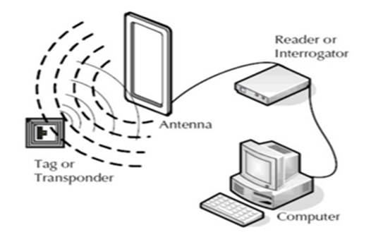
On the other hand, passive tags are often used on smaller objects since they are more beautiful, inexpensive, and compact. See Fig. 7 for an illustration of the passive RFID mechanism. This is how the procedure is carried out:
- The reader may easily access the tags.
- The reader uses its antenna to transmit an electromagnetic signal, which the passive tags subsequently pick up.
- An on-board capacitor stores the energy in passive tags.
- Inductive coupling transfers energy from the onboard capacitor to the tag’s coil.
- The reader demodulates the encoded radio wave that passive tags emit.
The operating frequency of passive RFID tags is lower, between 128 kHz to 915 MHz, and their communication range is rather restricted, ranging from a few inches to thirty feet.
Two major concerns with RFID technology are privacy and security. The ability to detect and follow the movement of RFID tags opens the door to the revelation of personal user data. Shoppers will be able to find out when they bought anything or how much it cost as soon as they step inside the detection range of the readers. We may deactivate the tags using the function of a “kill switch,” which will fix the problem.
Even if there were some issues during the installation of the technology, it is clear that RFID is a promising technology with great promise for supply chain management and item monitoring.
5.3 Medical Implants
The purpose of medical implants is to restore normal function to damaged organs and tissues by use of prosthetic devices that are either implanted into the body or placed on its surface. Implants may be surgically removed if they are used occasionally. Operations are performed during installation for those who utilise them on a permanent basis. Pacemakers and heart pumps are examples of low-power devices that require batteries, which need to be surgically replenished and replaced on occasion. Surgical procedures involving the insertion or removal of medical implants have the potential for catastrophic consequences. Further complications such as trauma, haemorrhage, infections, and anaesthetic difficulties may significantly affect individuals undergoing surgical procedures. So, it’s for the best if they have minimally invasive surgery.
When it comes to WPT technology, it can be used to charge medical implants wirelessly, doing away with the necessity for surgical replacements. It is usual to use near-field electromagnetic charging. Transmission coils cause gadgets to be cumbersome and expensive. At the moment, researchers are trying to figure out how to make the coil smaller and cheaper without sacrificing charging distance or efficiency.
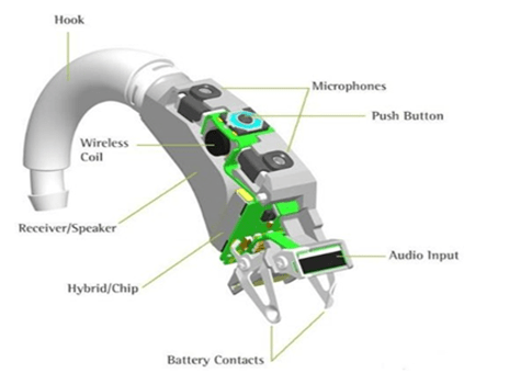
One common use of WPT on medical implants is the cochlear implant, as depicted in Figure 8. The two main components of a cochlear implant are an external microphone and transmission device and an inner ear receiver. An external signal processor powers the implant via an inductive link. Using WPT, you may easily change the batteries in the external transmitting system. The implant functions normally unless there is damage to the internal receiver. Cochlea implants have raised the level of life for millions of individuals throughout the world, and the market for them has already reached 1.5 billion dollars.
6. CONCLUSION
In conclusion, these transfer methodologies inductive coupling and magnetic resonance coupling that operate on the near field using electromagnetic induction have a short transfer range but are extremely simple to implement, making them ideal for portable devices. On the other hand, RF transfer that operates on the far field has a long effective power transmission range and is suitable for large-scale charging. WPT has brought a lot of new, exciting uses to our technology and made great strides in improving it over the last several decades. In this study, we have analysed wireless power transmission methods in great detail. The three most common transfer techniques are introduced first, and then their applications are discussed. Some difficulties persist in the course of putting this technology into practice. Consider the trend towards ever-smaller electronic devices. When employed in small electronic devices, WPT circuits may be rather space-consuming due to the number of coils, transistors, resistors, and capacitors they include. Conditions outside the device, like as the materials used, may also affect the propagation time. So, technological progress should lead to a little, effective solution that doesn’t cost a fortune. One way of looking at these issues is as potential avenues for investigation in the future.
REFERENCES
- AirFuel Alliance. (2022). AirFuel resonant standard.
- Bertoni, G., & Breban, L. (2020). Wireless power transfer for medical devices: State-of-the-art and perspectives. IEEE Transactions on Biomedical Engineering, 67(5), 1123-1134.
- Chabalko, M. J., & Teo, K. H. (2021). Advances in wireless power transfer systems for consumer electronics. Journal of Electrical Engineering & Technology, 16(2), 583-592.
- Cheng, D., & Lu, F. (2019). Highly efficient wireless power transfer systems for electric vehicles. IEEE Transactions on Power Electronics, 34(9), 8792-8802.
- Covic, G. A., & Boys, J. T. (2013). Inductive power transfer. Proceedings of the IEEE, 101(6), 1276-1289.
- Dhakar, L., & Ramakrishnan, V. (2022). A comprehensive review on wireless power transfer technologies. IEEE Access, 10, 56789-56800.
- Dhillon, H. S., & Zheng, Z. (2018). Performance analysis of RF-based wireless power transfer systems. IEEE Transactions on Wireless Communications, 17(7), 4740-4752.
- Fawole, O., & Ma, J. (2021). Safety and regulatory considerations in wireless power transfer for medical devices. Biomedical Signal Processing and Control, 68, 102730.
- Guo, J., & Liu, F. (2015). Overview of standards for wireless power transfer. Journal of Electromagnetic Waves and Applications, 29(18), 2345-2357.
- He, H., & Fan, Y. (2023). Emerging trends in wireless power transfer for wearable devices. IEEE Consumer Electronics Magazine, 12(1), 56-62.
- Huang, Q., & Lee, C. H. (2020). Wireless power transfer for industrial applications: An overview. IEEE Industrial Electronics Magazine, 14(3), 35-44.
- IEC. (2021). IEC 61980: Wireless power transfer for electric vehicles.
- IEEE Standards Association. (2019). IEEE standard for safety levels with respect to human exposure to radio frequency electromagnetic fields. IEEE Std C95.1-2019.
- Inoue, T., & Arai, H. (2016). Resonant inductive coupling for wireless power transfer: A review of recent progress. IEEE Journal of Electromagnetics, RF and Microwaves in Medicine and Biology, 1(1), 28-35.
- Ishida, T., & Kato, M. (2017). Application of wireless power transfer to implantable medical devices. IEEE Transactions on Microwave Theory and Techniques, 65(10), 3560-3571.
- Kim, J., & Park, J. (2020). Wireless power transfer technology for smart homes. IEEE Consumer Electronics Magazine, 9(4), 44-50.
- Kline, W., & Chan, K. (2018). Enhancements in wireless power transfer for electric vehicle applications. IEEE Transactions on Transportation Electrification, 4(1), 54-63.
- Lee, J. S., & Kim, S. (2019). Efficiency improvement techniques in wireless power transfer systems: A review. IEEE Transactions on Power Electronics, 34(9), 9144-9156.
- Li, X., & Zhang, Y. (2021). RF energy harvesting for wireless power transfer: Principles and applications. IEEE Access, 9, 8965-8981.
- Lim, S., & Lee, J. (2013). Magnetic resonance coupling for wireless power transfer: A review of recent advances. Journal of Electromagnetic Engineering and Science, 13(4), 203-213.
- Lu, F., & Mi, C. C. (2015). A review on high-power wireless power transfer for electric vehicles. Applied Energy, 180, 413-425.
- Nguyen, T. T., & Nguyen, H. H. (2022). Advanced wireless power transfer systems for electric vehicles: Technologies and standards. IEEE Transactions on Transportation Electrification, 8(2), 784-798.
- Park, C., & Kim, J. (2017). Wireless power transfer technology for implantable devices: An overview. Journal of Biomedical Engineering, 39(6), 873-888.
- SAE International. (2020). SAE J2954: Wireless power transfer for light-duty plug-in/electric vehicles and alignment methodology.
- Sample, A. P., & Smith, J. R. (2011). Experimental results with two wireless power transfer systems. IEEE Transactions on Power Electronics, 26(3), 669-678.
- Shen, Z., & Zhou, Z. (2022). Wireless power transfer: Recent advances and future prospects. Journal of Power Sources, 500, 229860.
- Sun, M., & Zhang, S. (2019). Review of standards and regulations for wireless power transfer technologies. IEEE Access, 7, 131337-131347.
- Wireless Power Consortium. (2023). Qi standard.
- Zhang, H., & Ma, Q. (2018). Safety considerations in wireless power transfer for medical applications. IEEE Transactions on Biomedical Engineering, 65(7), 1507-1515.
- Zheng, X., & Luo, H. (2020). Wireless power transfer technology for consumer electronics: An overview. IEEE Consumer Electronics Magazine, 9(2), 56-62.

Author –
Chitraansh Chaudhary | Welham Boys School
Follow us on social media for real-time news updates:


